

Action: Run program code
Upload code to the microcontroller
Select board and port
When compiling, a program is converted into machine language using a compiler. This means that the human-readable code (e.g., code written in the C++ programming language) is transformed into machine-readable code that the computer can understand.
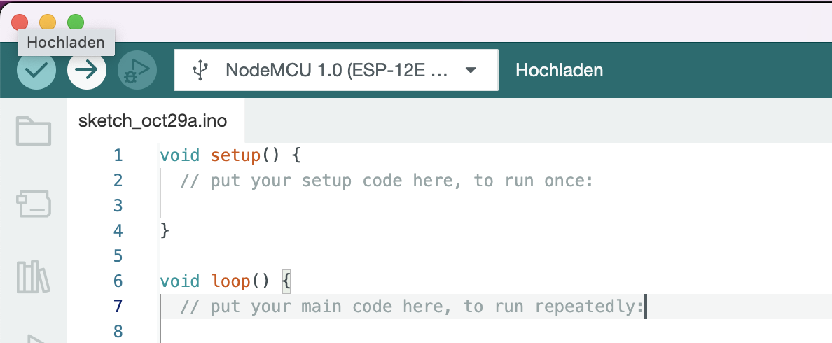
To let the Arduino IDE know, which Microcontroller the code should be compiled for, you need to select the board variant. In our case we are using a “NodeMCU 1.0 (ESP-12E Module)” or a “ESP32 Dev Module”.
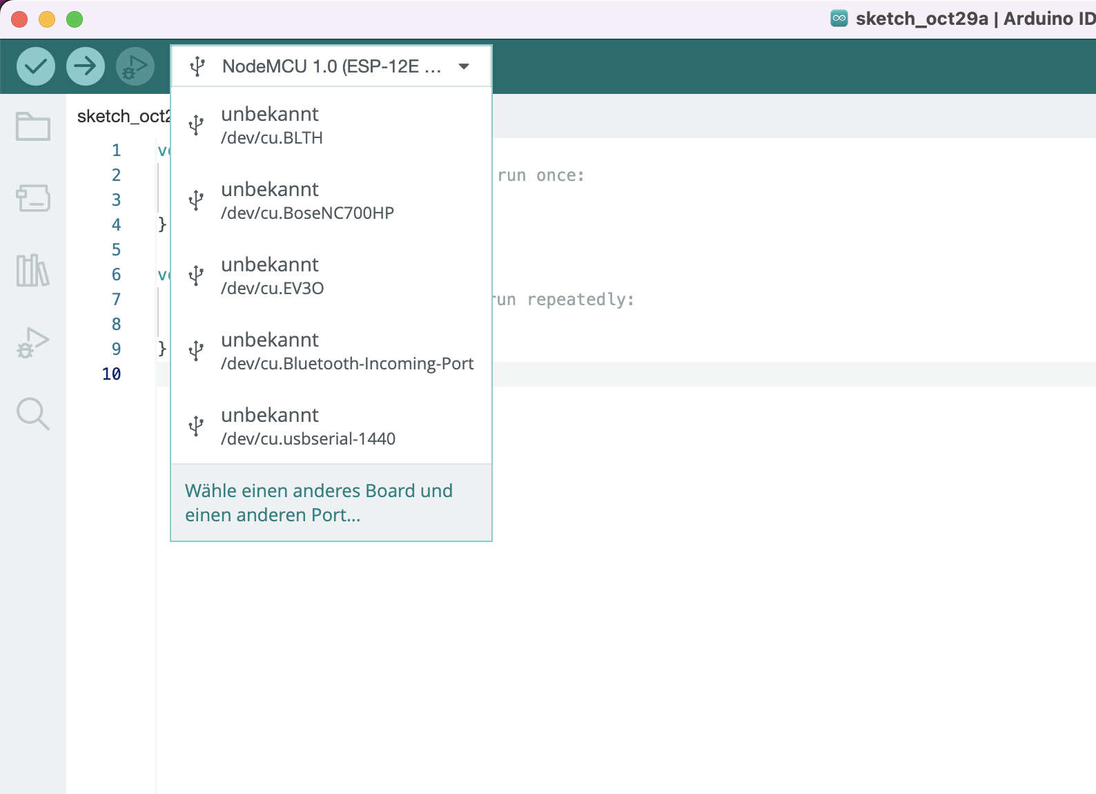
Connect the mikrocontroller via USB with your computer und select “Select other board and port…” to open the dialog.
Select board and port: Mac
In the dialog, you can search for “NodeMCU” and then select the board “NodeMCU 1.0 (ESP-12E Module)“. Additionally, choose the USB port to which the microcontroller is connected.
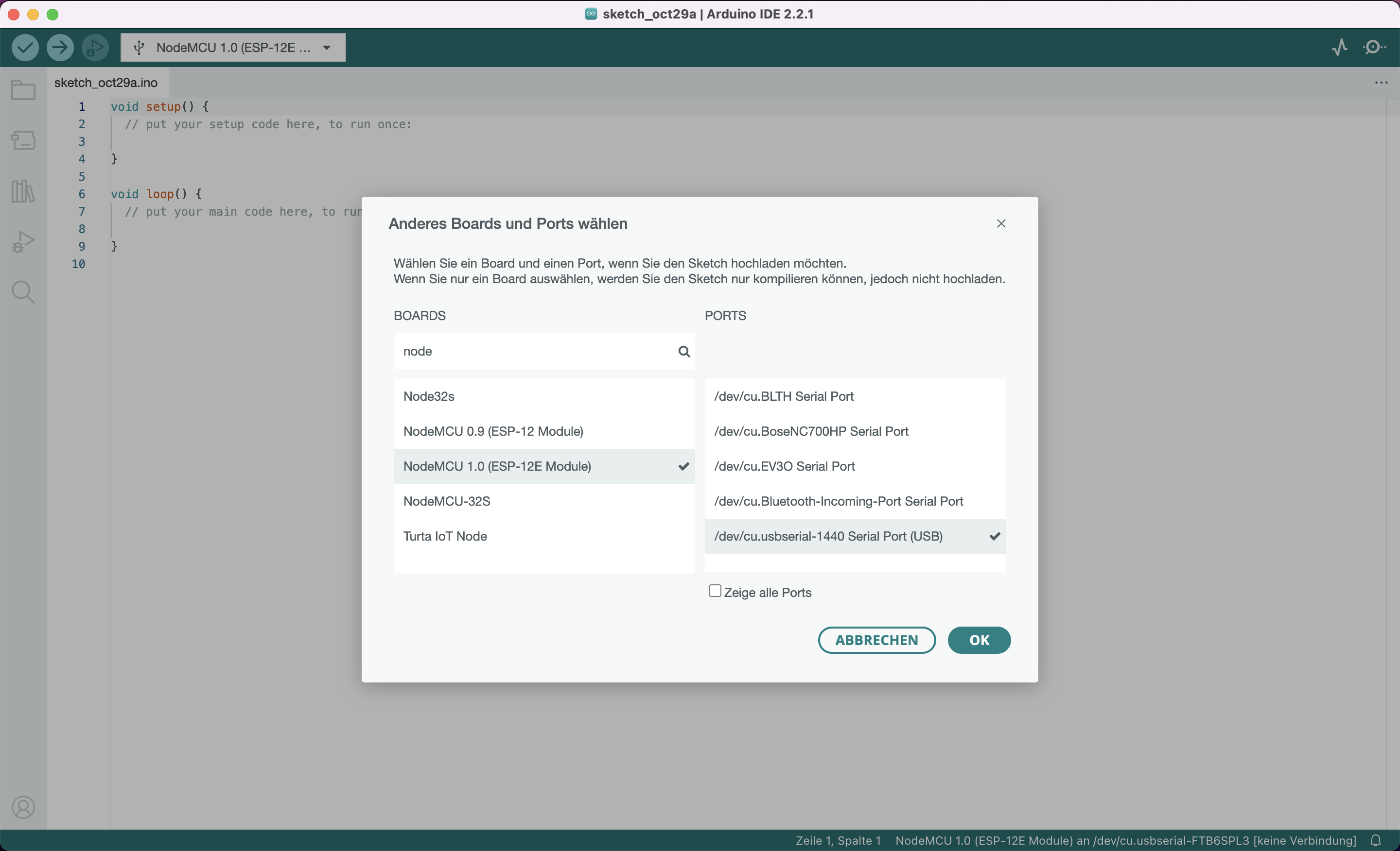
For ESP32, search for “ESP32 Dev Module” and select it.
Select board and port: Windows
In the dialog, you can search for “NodeMCU” and then select the board “NodeMCU 1.0 (ESP-12E Module)“. Additionally, choose the USB port to which the microcontroller is connected.
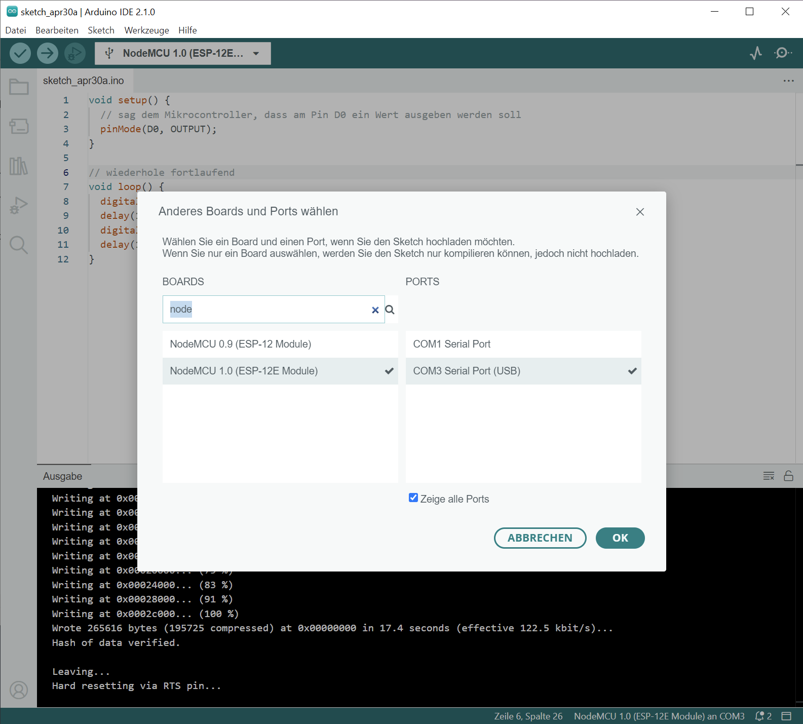
For ESP32, search for “ESP32 Dev Module” and select it.
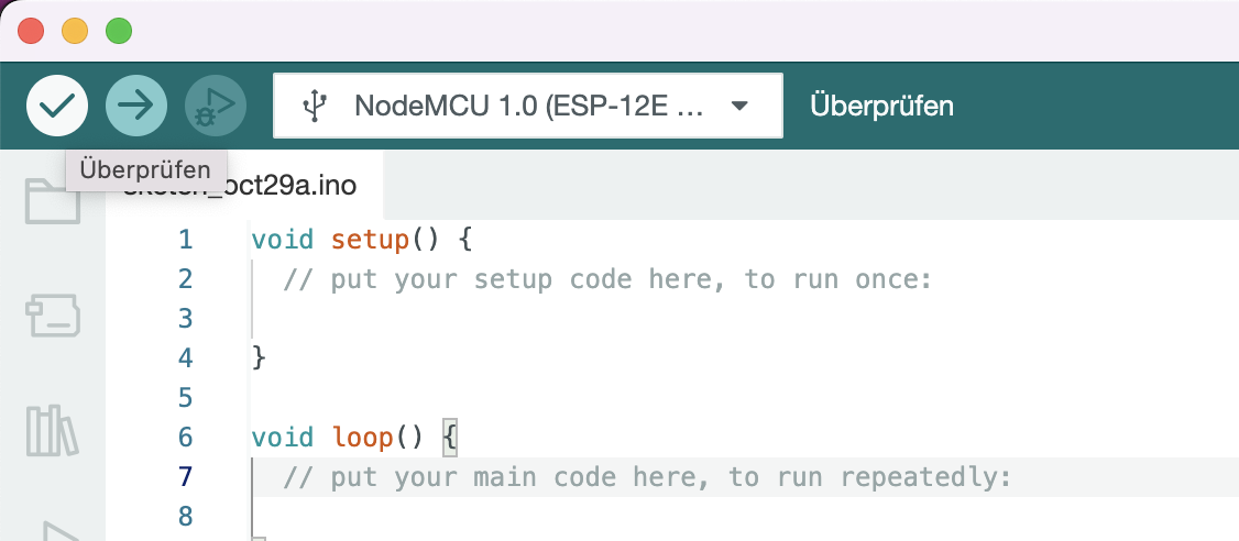
Compile the code
It’s possible to compile your code without uploading to the microcontroller by using the green “checkmark” in the top left corner of the Arduino IDE menu bar.
The Arduino IDE is trying to compile the code and will let you know if it was successful doing so.
If it wasn’t, an error message will appear, indicating what went wrong and highlighting the relevant line in red for you.
When you write code it makes sense to run this step once in a while to check the code and fix errors that come up.
Compile and execute
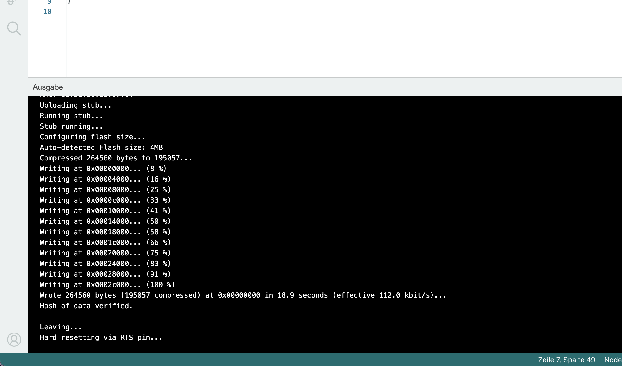
To compile and execute the code on the microcontroller in one step, click on the green “arrow” located at the top left of the Arduino IDE menu bar.
If you program was uploaded successfully you can see the following output in the Arduino-IDE:
Error messages
There is the possibility of connection errors when uploading the code to the microcontroller.
Failed to connect to ESP8266
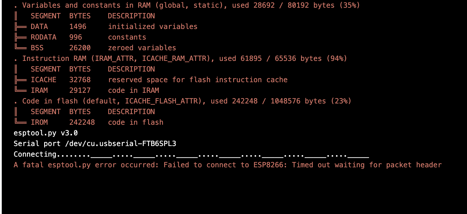
If you see this error, Arduino could not establish a connection to the microcontroller
You can try the following to resolve the error:
- remove the USB cable of the microcontroller from the computer. Press the FLASH button while inserting the USB cable again
or
- press and hold the RST (Reset) button of the microcontroller for 10 seconds
Try to upload the code again.
Your first program
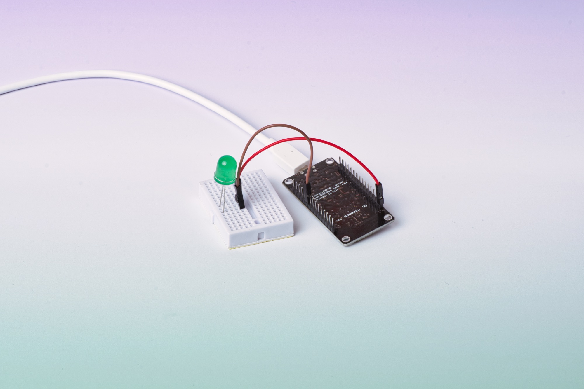
Create a circuit on the breadboard with an LED and use the microcontroller to make the LED blink. Blinking is achieved by turning the power on and off.
- Connect the USB cable to the microcontroller
- Connect the USB cable to your computer
- Place the LED on the breadboard as shown in the diagram
- Connect a cable to the G (Ground) pin on the microcontroller
- Connect a cable to the D0 pin on the microcontroller
- Connect a cable from the G pin to the short leg of the LED
- Connect a cable from the D0 pin to the long leg of the LED
ESP32 setup
- Connect the USB cable to the microcontroller
- Connect the USB cable to your computer
- Place the LED on the breadboard as shown in the diagram
- Connect a cable to the GND (Ground) pin on the microcontroller
- Connect a cable to the G23 pin on the microcontroller
- Connect a cable from the GND pin to the short leg of the LED
- Connect a cable from the G23 pin to the long leg of the LED
Great! Now we just need to write the code that will make the LED blink.
void setup() {
  // Sag dem Mikrocontroller, dass am Pin D0 ein Wert ausgeben werden soll:
  pinMode(D0, OUTPUT);
}

// Wiederhole fortlaufend
void loop() {
  digitalWrite(D0, HIGH);  // Setze den Pin D0 auf HIGH, um die LED anzuschalten.
  delay(1000);             // Warte eine Sekunde
  digitalWrite(D0, LOW);   // Setze den Pin D0 auf LOW, um die LED auszuschalten.
  delay(1000);             // Warte eine Sekunde
}
ESP32 code
Instead of D0, you need to use the pin number G23 for the ESP32 board.
void setup() {
  // Sag dem Mikrocontroller, dass am Pin D0 ein Wert ausgeben werden soll:
  pinMode(23, OUTPUT);
}

// Wiederhole fortlaufend
void loop() {
digitalWrite(23, HIGH); // Setze den Pin D0 auf HIGH, um die LED anzuschalten.
delay(1000); // Warte eine Sekunde
digitalWrite(23, LOW); // Setze den Pin D0 auf LOW, um die LED auszuschalten.
delay(1000); // Warte eine Sekunde
}
After you copied or typed the code into the Arduino-IDE, the code needs to be uploaded as described above. We suggest you type the code into the IDE and try to make sense out of it. This will help you learn.
Concrats! You wrote your first program and run it on the microcontroller. Now, think about how you can change the rhythm of the blinking LED and try to make small updates to the code.