

Action: Building a Circuit
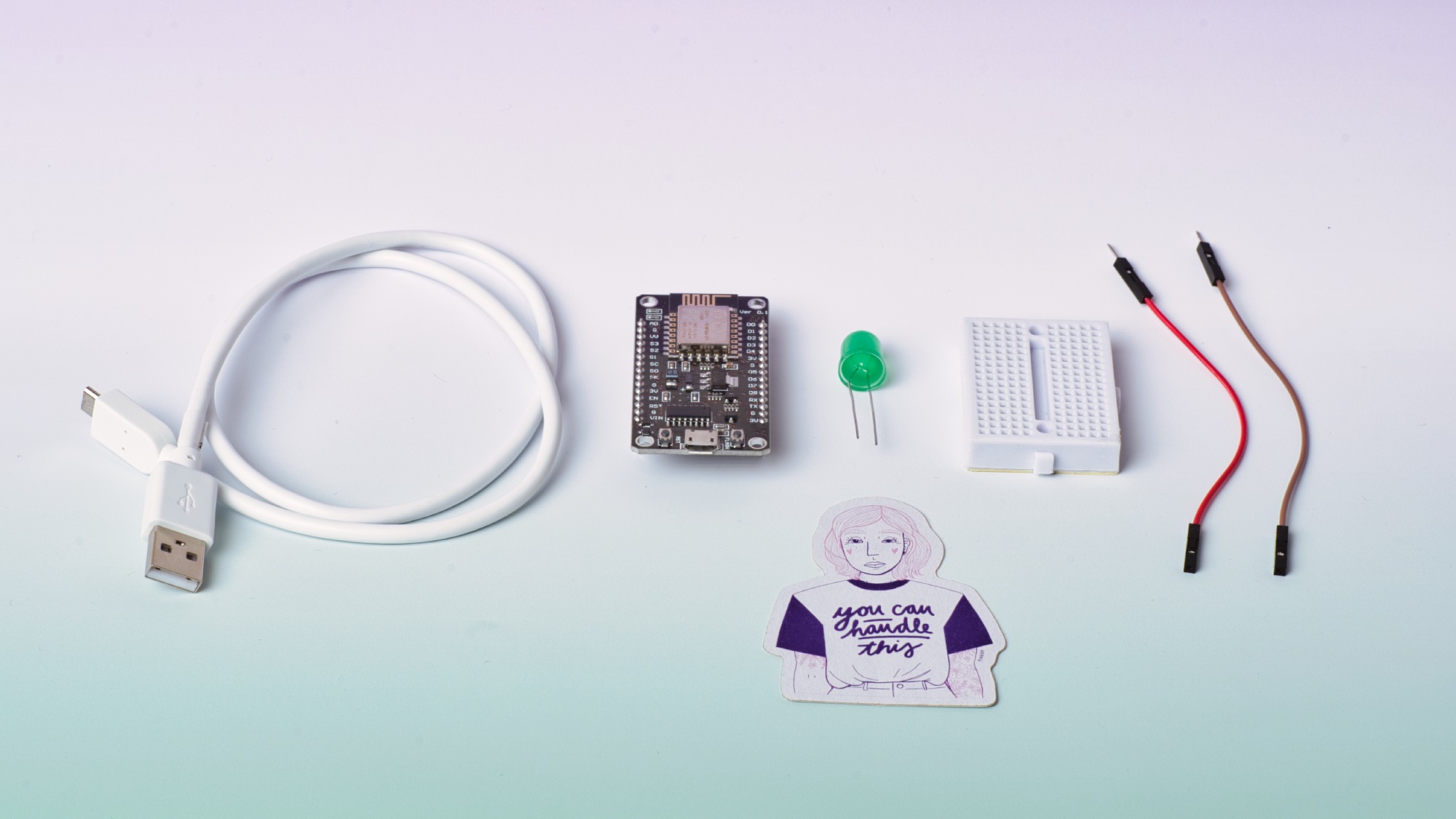
Create a circuit on the breadboard using an LED and use the microcontroller as the power source.
Note: The LED has one short leg and one long leg. The long leg (also called anode) is the connection for the negative terminal (ground) and the short leg (also called cathode) is the connection for the positive terminal (VCC) .
- Plug the LED onto the breadboard so that the legs of the LED are not in the same track of the breadboard. Be sure to note where the long (anode) and short (cathode) legs are on the breadboard.
- Now connect (independently from the breadboard) an MF cable to the GND (ground) slot on the microcontroller.
- Connect another cable to the 3V slot on the microcontroller.
- Now the microcontroller is connected to the LED on the breadboard. To do this, connect the cable attached to GND slot on the microcontroller to the shorter leg of the LED.
- Connect the cable attached to 3V slot on the microcontroller to the longer leg of the LED.
- Now the whole thing has to be connected to the power. First connect the USB cable to the microcontroller and then connect the USB cable to your computer.
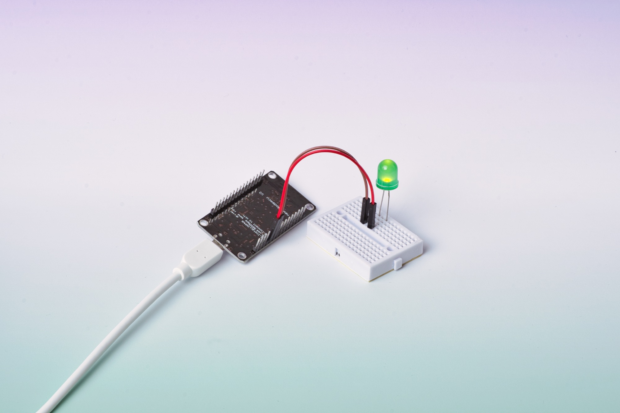
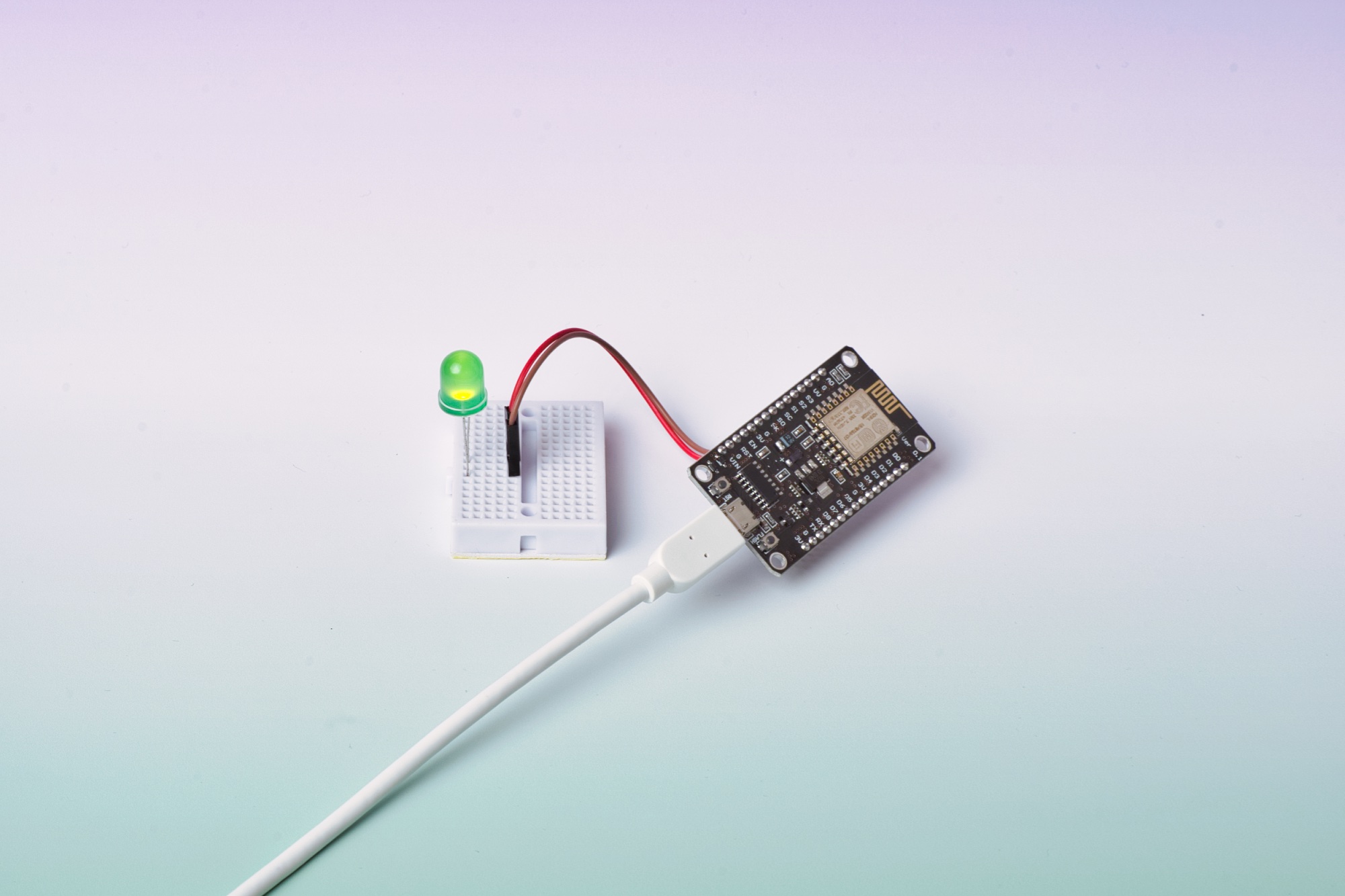
Great! 💫 You’ve built your first circuit. The LED should now light up. If it doesn’t, please check the connections and make sure they are properly placed in the correct slots. It’s also possible that the LED itself is defective.
Quiz
What could the microcontroller be replaced with, and the LED would still light up?