

Debugging and Troubleshooting
Debugging refers to the process of identifying errors or bugs in program code. Additionally, debugging can also be used for general troubleshooting of technical systems. The term “bug” originated from the time when computers consisted of large mechanical components interconnected to perform a specific task. When a malfunction was discovered during operation, caused by an insect, specifically a moth, getting trapped in one of the relays, engineers described the issue as a “bug” for the first time. The term stuck and is widely used today.
Debugging Steps
In projects that involve both software and hardware components, debugging is not always straightforward due to a variety of potential sources of errors. There could be faulty hardware components, circuitry setup issues, or bugs in the program code. It becomes particularly challenging when multiple errors occur simultaneously, making it difficult to pinpoint the exact problem.
- Learning debugging is necessary. But don’t worry, with more project experience, it will become easier for you to eliminate potential sources of errors.
- Software:
- Pay attention to error messages from the Arduino IDE (compiler or syntax errors).
- Use serial output to display the contents of a variable or other information during program execution.
- Isolate faulty program code.
- Check if parts of the program code are being executed.
- Hardware:
- Check the connections.
- Use a multimeter to verify connections.
- If necessary, replace a component to rule out any defects.
- Isolate parts of your setup to individually test their functionality.
Debugging with Serial Communication
Because you cannot see the values of your variables at a specific time or determine which part of the code is being executed during program execution, you can output this information using serial output. The serial output is displayed in a window of your IDE.
To configure the serial output, use this command in the setup method:
void setup() {
  Serial.begin(115200);
}
To output information through the serial output, use the command:
Serial.print("Schreibe dies in den seriellen Output")Debugging with a Multimeter
To check the circuit, using a multimeter is recommended.
You can:
- Test connections between wires/components
- Measure current strength
Continuity testing:
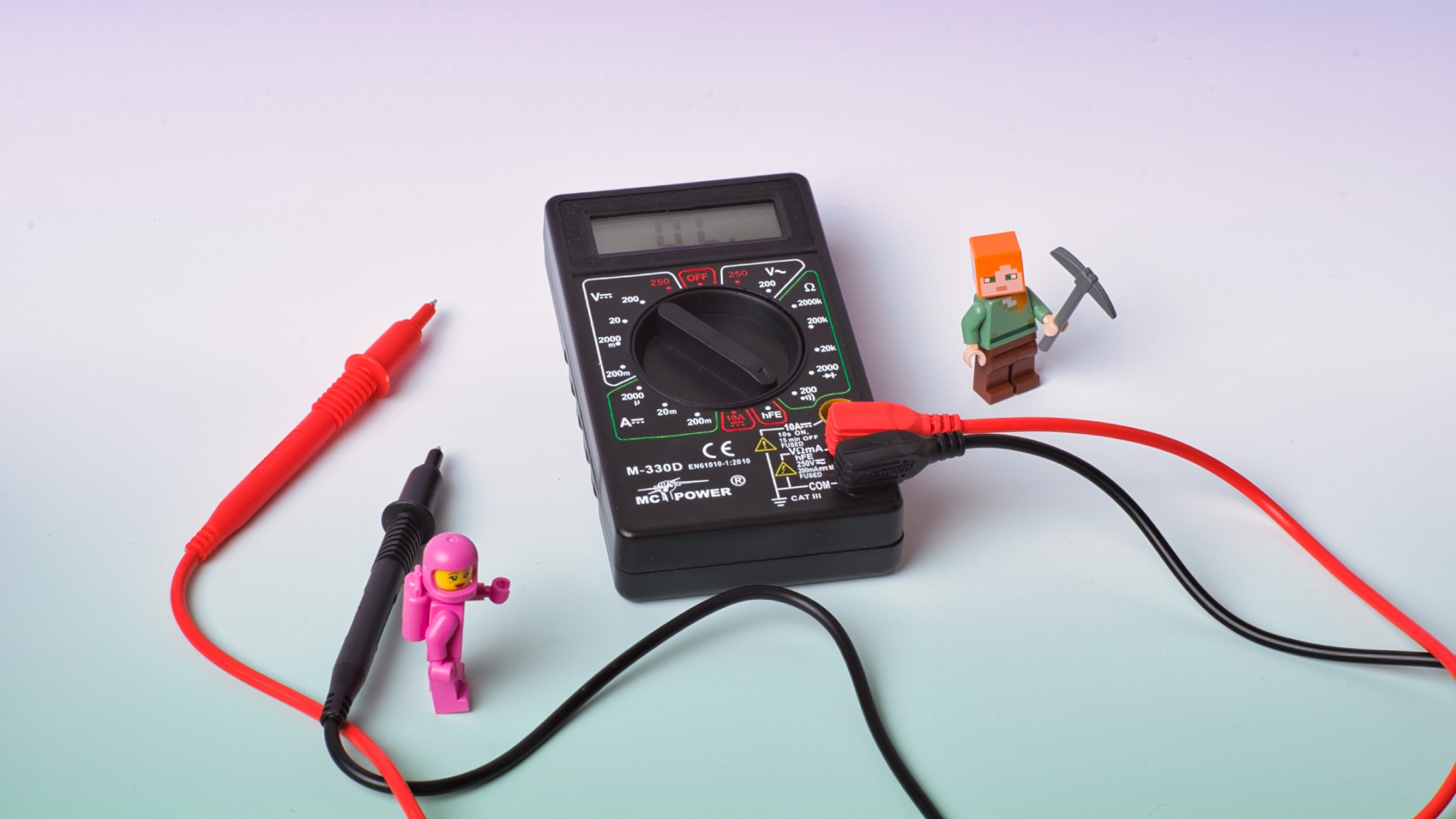
- Disconnect your setup from power.
- Connect the red probe to V”Ohm”mA and the black probe to COM.
- Set the rotary switch to the speaker symbol.
- Connect the two probes to two points of the wire being tested.
- If the measuring current flows through, the multimeter will produce an audible signal.
- The “OL.” indication on the display is not relevant for the measurement.
Measuring current strength (DC):
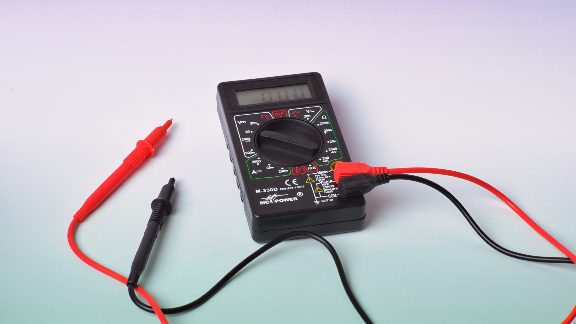
- Connect the red probe to V”Ohm”mA and the black probe to COM.
- Set the rotary switch to V=.
- If you know the measurement range, for example, ~3V, you can set the dial to 20.
- If the range is unknown, start with a higher range and then switch down until a meaningful value is displayed.
- The display will show the voltage value along with its polarity (as a sign).
Possible sources of error
- Microcontroller is not recognized by the computer.
- Failed to upload the program.
- SD card is not detected.
Microcontroller not recognized (Linux)
- One possible cause could be that the access permissions for the port are not configured correctly. On Ubuntu or Fedora, you can proceed as follows:
- In the command line, add the user to the dialout group:
sudo usermod -a -G dialout <username>- Restart the computer
- Start the Arduino IDE